St Andrews: 01334 850382
Glenrothes: 01592 654553
Email: info@rbgrant.co.uk
St Andrews: 01334 850382
Glenrothes: 01592 654553
Email: info@rbgrant.co.uk
R.B. Grant Electrical Contractors provide Power Factor correctors throughout Scotland from our Fife base. This system is used to reduce your bills, reducing the necessary power from the grid. We offer a free analysis and design service of your current electrical requirements. All of our work is carried out by experienced power factor correction electricians.
To correct the power factor, different kind of devices exist. Basically, we install a capacitor with the optimum size for your installation to compensate for the reactive power required by the load. The size of the capacitor will change as a function of the active power required by the installation, the current power factor and the power factor required.
We have solutions for either for single phase or tree-phase, for low voltage or medium voltage. Static or automatic solutions also exist as a function of your requirements. With an automatic capacitors' system, the correction will change as a function of the installation, but it’s more expensive.
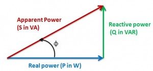
The Power Factor (PF) is the ratio of the real power (P in W) to apparent power (S in VA). Basically it’s the cosine of the phase angle called φ between the current and voltage wave-forms. Because it’s a cosine, the power factor can vary between 0 and 1. If a device has a positive angle as the current is lagging the voltage (between 0 and PI/2), it’s called inductive (a coil for example is a pure inductive equipment φ= PI/2).
 If a device has a negative angle (between 0 and –PI/2), it’s called capacitive (a capacitor is a pure capacitive equipment, φ= -PI/2). When the current and the voltage are in phase, the angle is 0. Look below for more explanations on the angle between the voltage and the current with the representation of the trigonometric circle:
This angle defines the different power of a device. Three types exist:
 In single phase system, P=U*I*cos(φ), Q= U*I*sin(φ) and S= U*I. The vector representation is thus:
So with that, we can say with the Pythagoras rule: S² = P² + Q² and cos(φ) = PF = P/S
In installations, different kind of devices include inductive loads like transformers, induction motors, induction generators and high intensity discharge lighting (HID). Consequently, the power factor reduces and the power required from the producer increases.
Basically, in the best working conditions, we want reactive power to be very small which has no useful function, but is necessary for the equipment to operate correctly. We also want active power almost equal to the apparent power.
Consequently, the power factor angle φ would approach zero. Thus the power factor cos(φ) would approach 1.
The explanation is given by the different power types. Indeed ,the active power P also called working power is the necessary power for a device to work. If we want working equipment, this power has to be sent. And the apparent power S represents the power sent by the producer. Consequently, your bill will change as a function of the apparent power.
Look at this example which shows an increase of the power factor angle:

The active power doesn’t move. To work, the device needs the same power. But if the power factor increases, the reactive power increases thus the apparent power increases too. So the greater the angle, the more you will have to pay for your equipment.
That is why special installations exists - to decrease the power factor angle (equivalent to increasing the power factor).


